Instructions for Rack & Pinion Kit
67-69 Camaro/Firebird, 68-74 Nova
Kit Parts: See Picture( 76ea. Total piece kit)
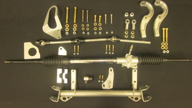
Rack & Pinion
Rack & Pinion Mount Assembly (Left Side)
Cross member: 1 ea.
U Joints: 3ea
Steering Shafts: 3 ea.
Steering Arms: 2 ea.
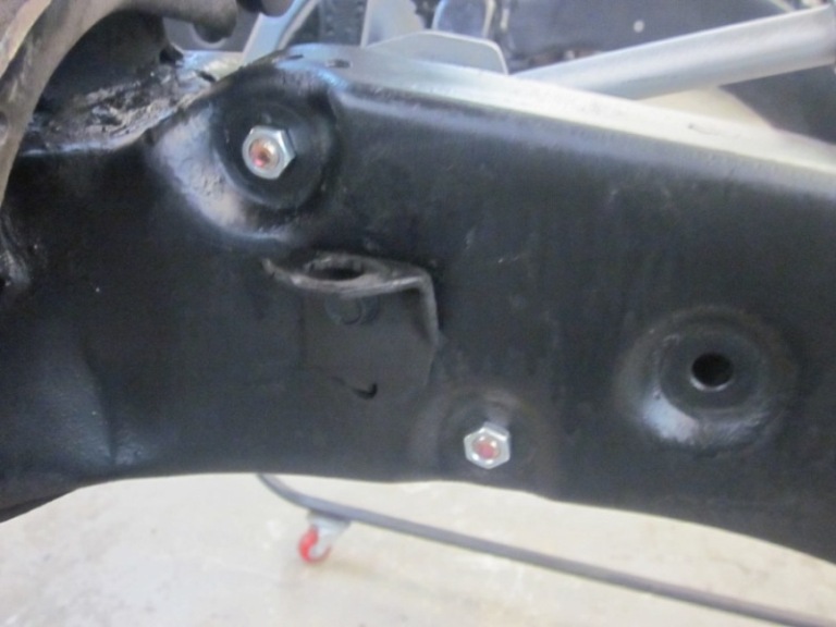
Steering bracket 1 ea. (goes on frame)
Steering Tube Mount 1 ea.
Rod ends 2 ea.
High Mis-alignment bushings 4 ea.
Stock A arms will take 4 ea. 5/16 thick (not included in kit)
Tubular A arms will take 2ea 5/16thick and 2ea 13/16 thick (not included in kit)
Bolt Kit:
½ x 4” 2 ea.
3/8 x 3 ¼ “ 2 ea.
7/16x 1 ½ 2ea
5/16x 2 ¼ 2ea
¼ x 1 ½ 6ea
¼ x ¾” 2ea.
½ x 3 1/2” 2 ea.
Washers and Locknuts as required.
Tools needed:
2 ¼ Hole Saw
Cut off Wheel
Assorted Socket/Wrench’s as required for typical bolts
Note: May Have to Lift Engine for access to some areas
Step 1:
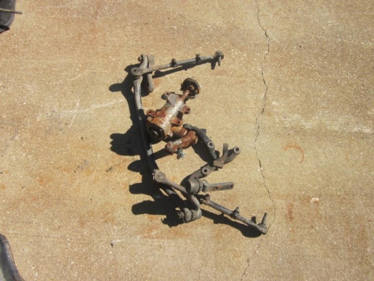
Remove all old steering assembly including steering arms.
Remove Drivers Side motor mount.
Remove front Lower A arm bolts
Step 2:
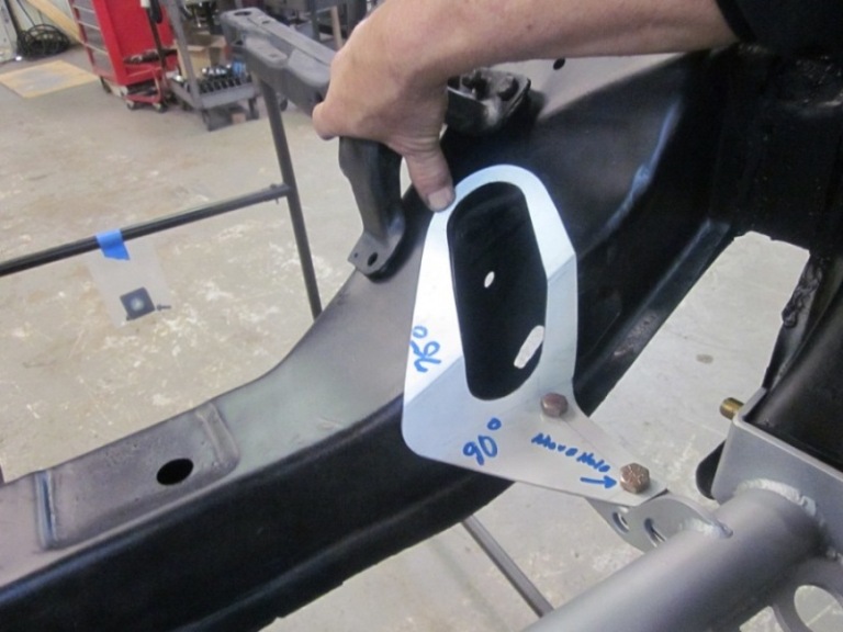
Layout lines from templates supplied (use level)
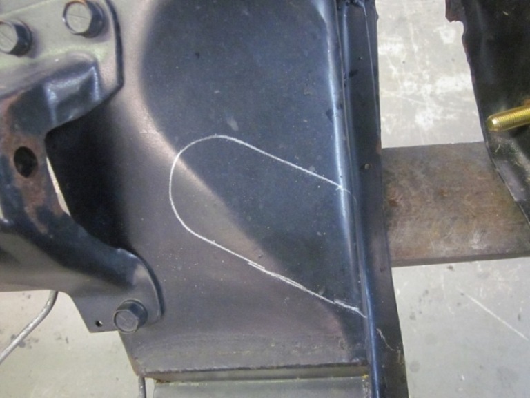
Center Punch 3 ea. holes for Hole Saw cut outs
Step 3:
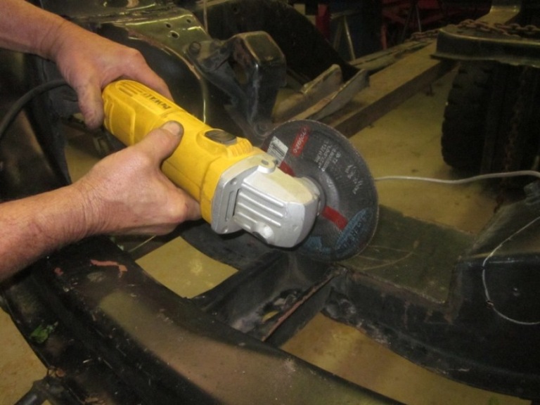
Cut off support bracket for front cross member ( runs front to rear)
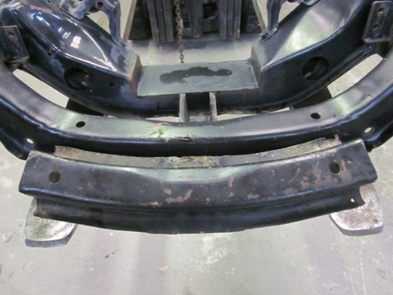
Cut off Front cross member where you have marked with templates (this will be taking out about 21”)
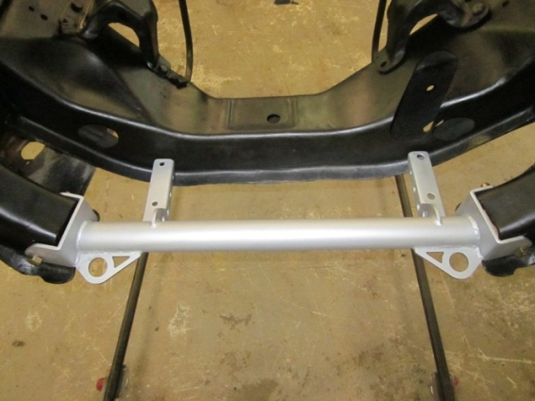
Test fit your new cross member and insert bolts where you have removed the lower front A arm bolts. Trim if you need to and weld if you want to along top ridge. (welding not required)
Step 4:
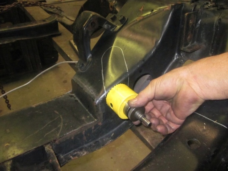
Drill pilot holes for 2 ¼ hole saw/ 3 locations 2 on top front of K member and one on the rear. (for steering shaft run thru)
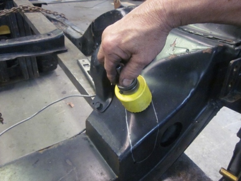
Hole saw same locations
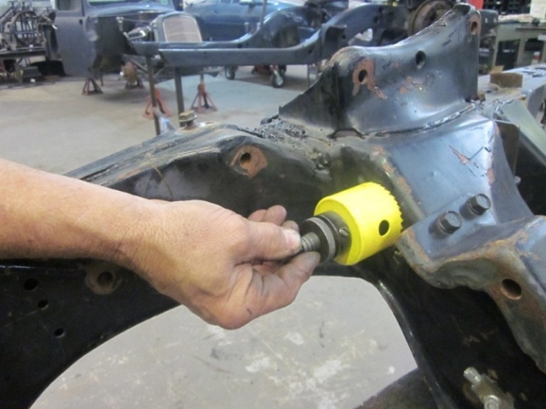
Cut out area between the holes you have just cut per the provided template you have already laid out.
Step 5:
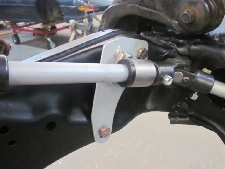
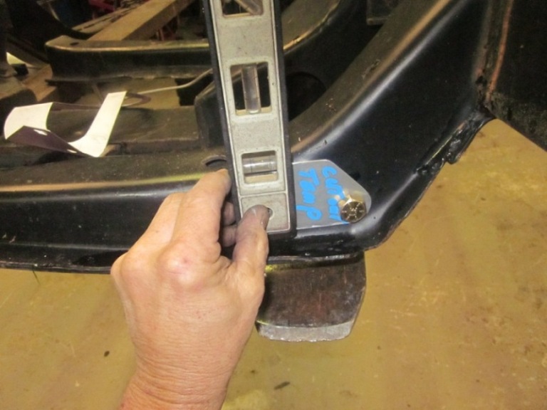
Install Steering mount bracket to frame with supplied bolts all the way thru the frame (existing holes) and install and tighten nuts as required.
(Note: This bracket has slots for some adjustability so align as required)
Assemble steering shaft as shown and secure bolts and slide thru new location holes.
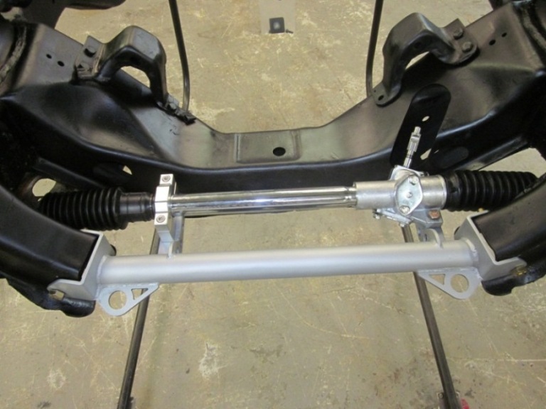
Slide Rack onto new mount to trial fit on to new steering joints. (make sure you have proper clearance. (Note: Rack must be loose in order for the rack can receive new steering u joint) Do not tighten rack before assembly to help line everything up.
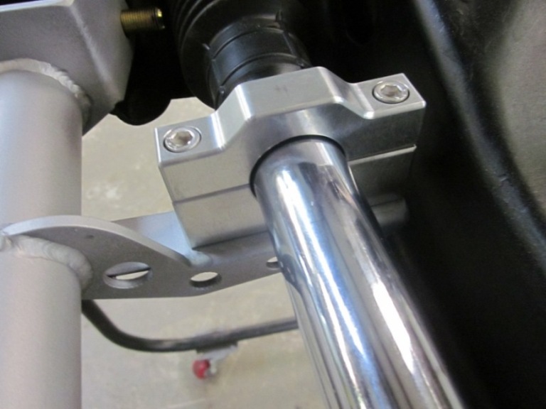
Install rack with new aluminum rack mount brackets, left side only. The right side will bolt directly to the crossmember.
You may at this time tighten up rack and turn steering shaft to check fitment.
Step 6:
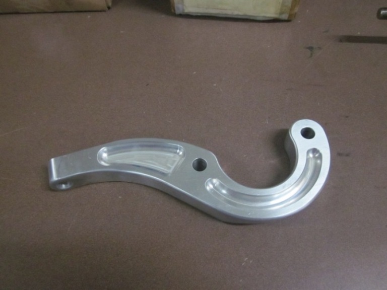
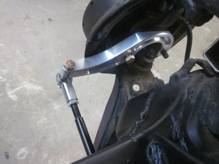
Install steering arms facing towards front of car and install high mis-alignment rod ends to new aluminum steering arm ends and rack.
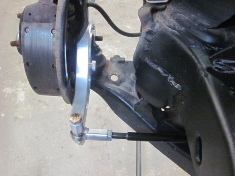
Note: Check for rubber boot clearance as some times you may have to trim a small amount of clearance so the boot does not rub. Turn steering back and forth and look at the boot area closely and trim with small hand grinder if required.
Final:
You may at this time complete your final assembly and check all bolts and all clearance. It should turn smooth with no binding etc. Torque all bolts as required. You may want to remove all parts and powder coat or paint as required at this time.
A steering column modification will be needed in order to complete this install to the 3/4 shaft.Cut off rag joint and slide new shaft “inside” existing steering column. You may at this time drill steering column and shaft and install supplied single bolt. You may weld if desired.
( Note before the above task is done make sure your steering wheel/alignment is set and straight as you require for steering wheel placement.) Also Some Modification required when using Factory Control arms.